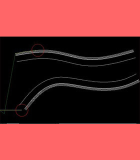
The software features
The function of this software is to generate the G code from the graph drawn by the user suitable for the woodworking curve sawing machine and bilateral woodworking milling machine.
The graph drawn by the user will be generated the cutting code of the board from bottom to top. At the same time, the direction of the saw blade should be the tangent direction of the current saw blade. And it is necessary to ensure that saw cutting line can be cut which can not exceed in the middle of multiple boards. It is also necessary to ensure that no line can be stopped on the board. If it stops in the middle, return to the starting point according to the original path and cut another line. The tool's empty trip cannot pass through uncut boards.
Woodworking bilateral automatic milling programming function which is the user first draws the path of bilateral machining in the CAD software and transfers it to the software.
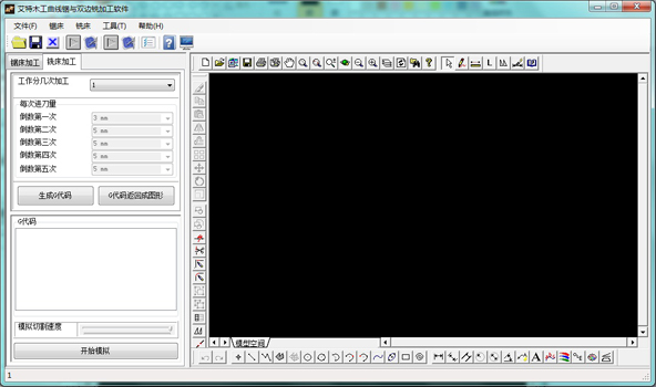
The software will set the process path of bilateral milling according to the number of machining cutting times and the amount of feed of each time set by the user. Process and mold the two sides of the workpiece at one time. At the same time, the front and back positions of the left and right milling cutters can be set according to different machines, so that the left and right milling cutters can be asynchronous follow-up.
The minimum hardware and software requirements of software running
Hardware requirements
INTEL or AMD processor above 1GHz
The memory is not less than 2Gb
Hard disk capacity more than 10Gb
Have a built-in or separate graphics card
Software requirements
WIN XP or WIN7 system.
With FRAMEWORKS3.5 operating environment system.
The corresponding drawing software.
Part of the software and use instructions
The interface of this software as shown below:
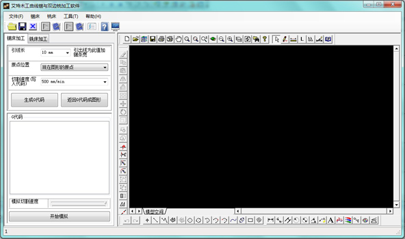
As soon as the software opens, it enters the programming interface of woodworking curve saw. Users can click the "milling machine processing" button to enter the woodworking milling machine processing interface. As shown below:
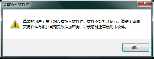
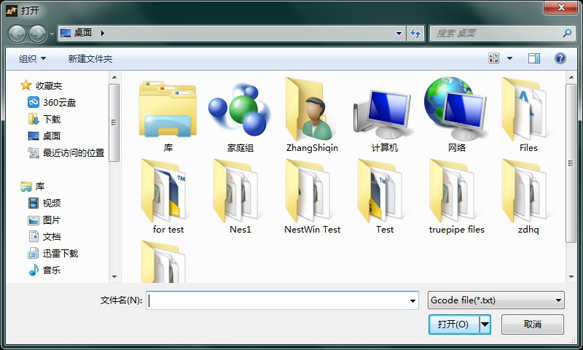
If software is opened without inserting software dongle, dialog box will pop up as follows to remind users. As shown below:
Code generation of woodworking curve saw
The function of woodworking curve saw can generate the G code format from the curve drawn by the user that can be recognized by woodworking curve sawing machine according to certain requirements. The user can draw the curve to be processed in CAD software, and then open it in this software. As shown below:
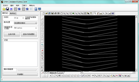
Because the real wood is different from the one in the picture, we need to set a certain length of incoming line (default to be 10mm) to prevent saw blade damages when it touches the raw material by mistake while moving the machine tool.The user can set the length according to the need.
The origin position is the initial position of the cutter. The user can have the following options.
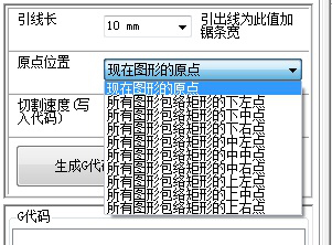
The cutting code speed is the speed of the code control sawing machine process. This speed is the maximum processing speed of the sawing machine. The velocity decreases when the curvature of the processed curve is large. The greater the curvature, the lower the velocity. The velocity defaults to be 500mm/min. The user can set it by himself.
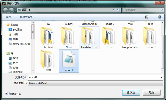
The software will automatically generate G code from graphics in the drawing area when the user clicks the “generate G code” button. If the user selects a part of the graphics primitive and click the button, only the selected graphics primitive will be generated into the G code. If the user did not select any graphics primitive, the software will generate G code of all the graphics primitive of the current drawing area.
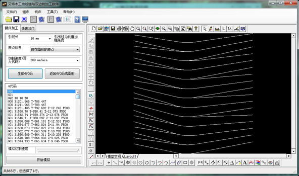
The drawing area will show the cutting state when the machine executes this line of code, when the user clicks the code item in the G code window. As shown below:
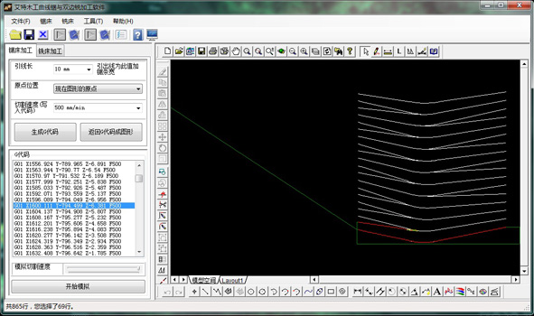
G code of woodworking curve saw back into graphics
Click to “return G code into graphic” button. The form appears as shown below:
The code in the software as shown below:
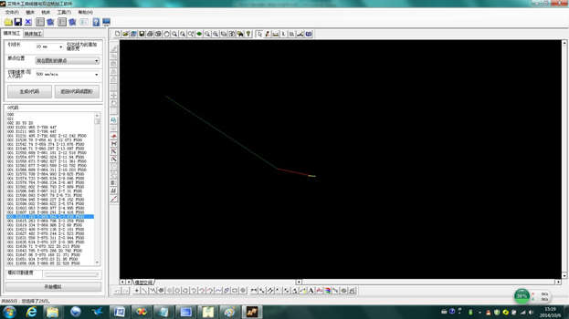
If the user wants to see how this code performs on the machine, he can manually click the “G code item” or click the "start simulation" button. So that the software can execute the code automatically and display the graphics in the drawing area for the user to check. As shown below:
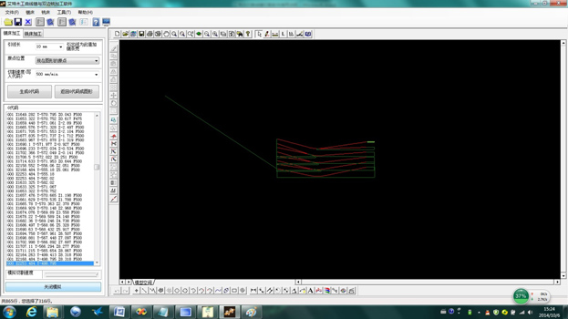
After the simulation starts, the “start simulation” button is changed to “close the simulation”. If the user clicks "close the simulation" button, then the software stops the simulated cutting.
